产品分类
更多 >已有 4 人关注
买家还看了
身份验证:
经营模式:
注册资本:万元
企业类型:有限责任公司
所在地区:广东 深圳 宝安区 大浪德利威工业园4楼
联 系 人:谢女士(先生)

联系电话:139****0381
产品分类
更多 >最新上架
更多 >
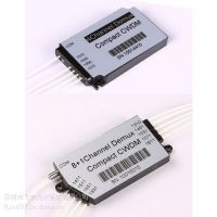
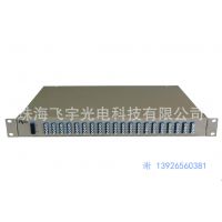
Flyin Optronics’ 100GHz dense wavelengthpision multiplexer (DWDM module) utilizes thin film coating technology andproprietary design of non-flux metal bonding micro optics packaging to achieveoptical add and drop at the ITU wavelengths. It provides ITU channel centerwavelength, low insertion loss, high channel isolation, wide pass band, lowtemperature sensitivity and epoxy free optical path . It can be used forwavelength add/drop in telecommunication network system.
Features
l Low Insertion Loss
l Wide pass band
l High Channel Isolation
l High Stability andreliability
l Epoxy-free on OpticalPath
Applications
l Channel Add/Drop
l DWDM Network
l Wavlength Routing
l Fiber Optical Amplifier
l CATV fiberoptic System
OpticalSpecification (Flattop AWG)
Parameters | Condition | Specs | Units | ||
Min | Typ | Max | |||
Number of Channels |
| 40 |
| ||
Number Channel Spacing | 100GHz | 100 | GHz | ||
Cha. Center Wavelength | ITU frequency. | C -band | nm | ||
Clear Channel Passband |
| ±0.1 | nm | ||
Wavelength Stability | Maximum range of the wavelength error of all channels and temperatures in average polarization. | ±0.05 | nm | ||
-1 dB Channel Bandwidth | Clear channel bandwidth defined by passband shape. For each channel | 0.4 |
|
| nm |
-3 dB Channel Bandwidth | Clear channel bandwidth defined by passband shape. For each channel | 0.6 |
|
| nm |
Optical Insertion Loss at ITU grid | Defined as the minimum transmission at ITU wavelength for all channels. For each channel, at all temperatures and polarizations. |
| 4.5 | 6.0 | dB |
Adjacent Channel Isolation | Insertion loss difference from the mean transmission at the ITU grid wavelength to the highest power, all polarizations, within the ITU band of the adjacent channels. | 25 |
|
| dB |
Non-Adjacent, Channel Isolation | Insertion loss difference from the mean transmission at the ITU grid wavelength to the highest power, all polarizations, within the ITU band of the nonadjacent channels. | 30 |
|
| dB |
Total Channel Isolation | Total cumulative insertion loss difference from the mean transmission at the ITU grid wavelength to the highest power, all polarizations, within the ITU band of all other channels, including adjacent channels. | 22 |
|
| dB |
Insertion Loss Uniformity | Maximum range of the insertion loss variation within ITU across all channels, polarizations and temperatures. |
| 1.0 | 1.5 | dB |
Directivity(Mux Only) | Ratio of reflected power out of any channel(other than channel n)to power in from the input channel n | 40 |
|
| dB |
Insertion Loss Ripple | Any maxima and any minima of optical loss across ITU band, excluding boundary points, for each channel at each port |
|
| 0.5 | dB |
Optical Return loss | Input & output ports | 40 |
|
| dB |
PDL/Polarization Dependent Loss in Clear Channel Band | Worst-case value measured in ITU band |
| 0.3 | 0.5 | dB |
Polarization Mode Dispersion |
|
|
| 0.5 | ps |
Maximum Optical Power |
|
|
| 23 | dBm |
MUX/DEMUX input/ output Monitoring range |
| -35 |
| +23 | dBm |
IL Represents the worst case over a+/-0.1nm window around the ITU wavelength
PDL was measured on average polarizationover a +/- 0.1nm window around the ITU wavelength.
Ordering Part CodeSequence
AWG | X | XX | X | XXX | X | X | X | XX |
| Band | Number of Channels | Spacing | 1st Channel | Filter Shape | Package | Fiber Length | In/Out Connector |
C=C-Band L=L-Band D=C+L-Band X=Customize | 16=16-CH 32=32-CH 40=40-CH 48=48-CH XX=Special | 1=100G 2=200G 5=50G X=Special | C60=C60 H59=H59 C59=C59 H58=H58 XXX=special | G=Gaussian B=Broad Gaussiar F=Flat Top | M=Module R=Rack X=Special | 1=0.5m 2=1m 3=1.5m 4=2m 5=2.5m 6=3m S=Specify | 0=None 1=FC/APC 2=FC/PC 3=SC/APC 4=SC/PC 5=LC/APC 6=LC/PC 7=ST/UPC S=Specify |

相关推荐
更多 >
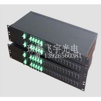
供应DWD密集波分复用系统 IDC 数据链路 基站 光纤入户 多路业务单纤传输

供应3端口滤波片型波分复用器(1310/1490/1550nm)
本页面所展现的 供应19“1U机架式 40通道 AWG Mux Demux 信息及其他相关推荐信息,均来源于其对应的商铺,信息的真实性、准确性和合法性由该信息的来源商铺所属企业完全负责。龙智造工业云对此不承担任何保证责任。
建议您在购买相关产品前务必确认供应商资质及产品质量,过低的价格有可能是虚假信息,请谨慎对待,谨防欺诈行为。 建议在搜索产品时,优先选择皇冠会员,皇冠会员为龙智造工业云VIP会员,信誉度更高。
市场商务
023-85238885客服热线
400-008-2859